![[cover]](boymech_title.jpg)
The Boy Mechanic
This document last edited June 8 2010. Content (c) Herb Johnson, notwithstanding expired copyrights of the source material. See some 21st century restoration from this home Web page.
![[cover]](boymech_cover.jpg)
![[inside title]](boymech_ii.jpg)
"The Boy Mechanic" is one of many compliations of short how-to articles from Popular Mechanics, a monthly magazine of the late 19th century, still in publication today. This book was published in 1913. These article show what millions of young men (and likely some women) did with their spare time, in an era where more and more of them would likely work in factories, repair and run farm equipment, or possibly become tradesmen, mechanics, engineers or scientists. Many more would simply become hobby mechanics, or at least complete a few of the projects. (Pardon the pro-male gender bias, it was part of the times.)
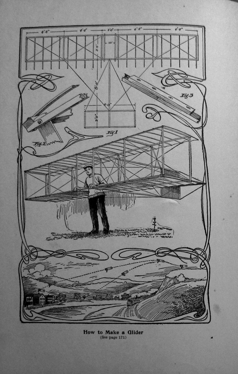
Of the 800 or so projects in this book, many are outright dangerous by today's standards. Here's an illustration of a hang glider, the article shows the general construction of it. materials in other projects include acids (to revive batteries), electric shock (to scare cats or shoo mice), furnaces (to melt metal), and high voltage (early radio, sparks, electrostatics). All were popular interests of the era.
So many of these books were printed, and such is the lack of interest in small mechanical projects today, that books like this can be bought for dollars, especially if they are worn. Printed on ordinary book paper, this century-old edition is already yellow as the paper's acids eat it up. In another century books like this will simply crumble. The magazines of the same age are in worse condition. - Herb Johnson
A Model Steam Engine
Image of actual article are on page 1 and page 2.
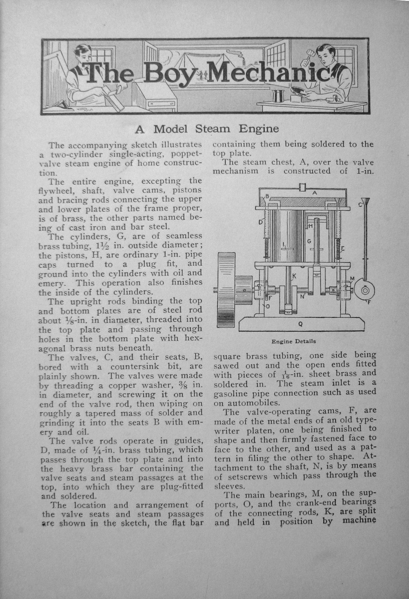
![[steam engine]](boymech_steam1.jpg)
The accompanying sketch illustrates a tw~cylinder single-acting, poppet-valve steam engine of home construction.
The entire engine, excepting the flywheel, shaft, valve cams, pistons and bracing rods connecting the upper and lower plates of the frame proper, is of brass, the other parts named being of cast iron and bar steel.
The cylinders, G. are of seamless brass tubing, 1-1/2 in. outside diameter; the pistons, H. are ordinary 1-in. pipe caps turned to a plug fit, and ground into the cylinders with oil and emery. This operation also finishes the inside of the cylinders.
The upright rods binding the top and bottom plates are of steel rod about 1/8-in. in diameter, threaded into the top plate and passing through holes in the bottom plate with hexagonal brass nuts beneath.
The valves, C, and their seats, B. bored with a countersink bit, are plainly shown. The valves were made by threading a copper washer, 3/8 in. in diameter, and screwing it on the end of the valve rod, then wiping on roughly a tapered mass of solder and grinding it into the seats B with emery and oil.
The valve rods operate in guides, D, made of 1/4-in. brass tubing, which passes through the top plate and into the heavy brass bar containing the valve seats and steam passages at the top, into which they are plug-fitted and soldered.
The location and arrangement of the valve seats and steam passages are shown in the sketch, the flat bar containing them being soldered to the top plate.
The steam chest, A, over the valve mechanism IS constructed of 1-in. square brass tubing, one side being sawed out and the open ends fitted with pieces of 1/16-in. sheet brass and soldered in. The steam inlet is a gasoline pipe connection such as used on automobiles.
The valve-operating cams, F. are made of the metal ends of an old typewriter platen, one being finished to shape and then firmly fastened face to face to the other, and used as a pattern in filin the other to shape. Attachment to the shaft, N. is by means of setscrews which pass through the sleeves.
The main bearings, M, on the supports, O. and the crank-end bearings of the connecting rods, K, are split and held in position by machine screws with provision for taking them up when worn.
The exausting of spent steam is accomplished by means of slots, I, sawed into the fronts of the cylinders at about 1/8-in. above the lowest pOsition of the piston's top at the end of the stroke, at which position of the piston the valve rod drops into the cut-out portion of the cam and allows the valve to seat. All the work on this engine, save turning the pistons, which was done in a machine shop for a small sum, and making the flywheel, this being taken from an old dismantled model, was accomplished with a hacksaw, bench drill, Carborundum wheel, files, taps and dies. The base, Q. is made of a heavy piece of brass.
The action is smooth and the speed high. Steam is Supplied by a sheet brass boiler of about 3 pt. capacity, heated with a Bunsen burner — Contributed by Harry F. Lowe, Washington D. C.
Quartz Electrodes Used in Receiving Wireless Messages
![[quartz detector]](boymech_quartz.jpg)
Wireless messages have been recieved at Washington DC from Key West, Florida, a distance of 900 miles, through a receiving instrument in which two pieces of quartz of different composition were used on the electrodes. in making an instrument of this kind the quartz can be purchased from a dealer in minerals. One piece must contain copper pyrites and the other zincites. The electrodes are made cupping to hold the minerals and each should have a screw adjustment to press the pieces of quartz in contact with each other. Connect as shown..with a high-resistance reciever.... — Contributed by Harry F. Lowe, Washington D. C.
Modern physics would say that the contact between the two quartz pieces constitutes a semiconductor diode. Copper and iron pyrite is called chalcopyrite; it has possibilities for solar cells as a photoactive semiconductor. Zincite has semiconductor and piezoelectric properties, and is noted in many early 20th century references for use as a "Perikon" or Cat's Whisker detector, as referenced in Wikipedia.
contact the author via email links at this Web page.
Copyright © 2010 Herb Johnson