![[AP Products]](ap_early_bb.jpg)
This page was last updated Dec 15 2025 (c) Herb Johnson all rights reserved. Search my Web site to find other Web page content of interest. My home Web page for restoration of vintage computing is at this link.
In March 2023 I started this Web page, to describe restoration and use of various digital and analog breadboards produced in the 1970's, which I acquired. They are still useful in the 21st century to test components and to prototype simple circuits. They were incorporated into training documents and educational programs. Over time, I've acquired and added more products here, also products I don't have but others tell me about.
To get an idea of how and why these were used, look inside 1960's and 70's and 80's "hobby electronic" and "popular science" and other magazines of the era. They have ads and articles about these tools and programs. In the era, these were among several self-education programs sold by companies, to train technicians and encourage future engineers. Thanks to Korean and Vietnam veteran's benefits, many people who bought these kits, qualified for government reinbursement as educational tools. Also, many trade schools, high-school programs, and small colleges used these products and courses. Heathkit provided lots of products to those programs, with a higher-grade line of tools for university electronics labs.
Today, these breadboards may be good ways to learn how to use an oscilloscope. Follow the link to see what I mean. I've used a lot of other test equipment myself, and I have some equipment available.
I picked up this early AP Products breadboard at a hamfest in Bristol PA in May 2024. I can't find any references to it on the Web. There's no product number. The various sections of it are red, black, yellow, blue. They can be rearranged on the grey backplate. It has the AP logo on the back. The bus bars connecting the pins look gold-plated. It measures 3 X 6 inches. Possibly it's a part of some kit, or maybe an educational tool.
In Feb 2025, Rick Kready identified this product as an AP brand "Hobby-Blox" product. Here's pages from a 1981 catalog for this breadboarding system.
I obtained a number of them on eBay in 2025.
![[E&L CD1]](el_cd1hart_1.jpg)
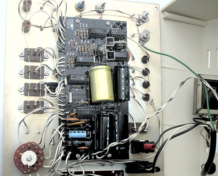
Here's an E&L CD1 breadboard, from the mid-1970's. It supports both TTL prototyping, and CMOS prototyping at voltages above TTL's 5-volt operations. This is from Lee Hart, June 2023. Here's how he checked it out, reviewed the design, and made repairs and modifications. - Herb
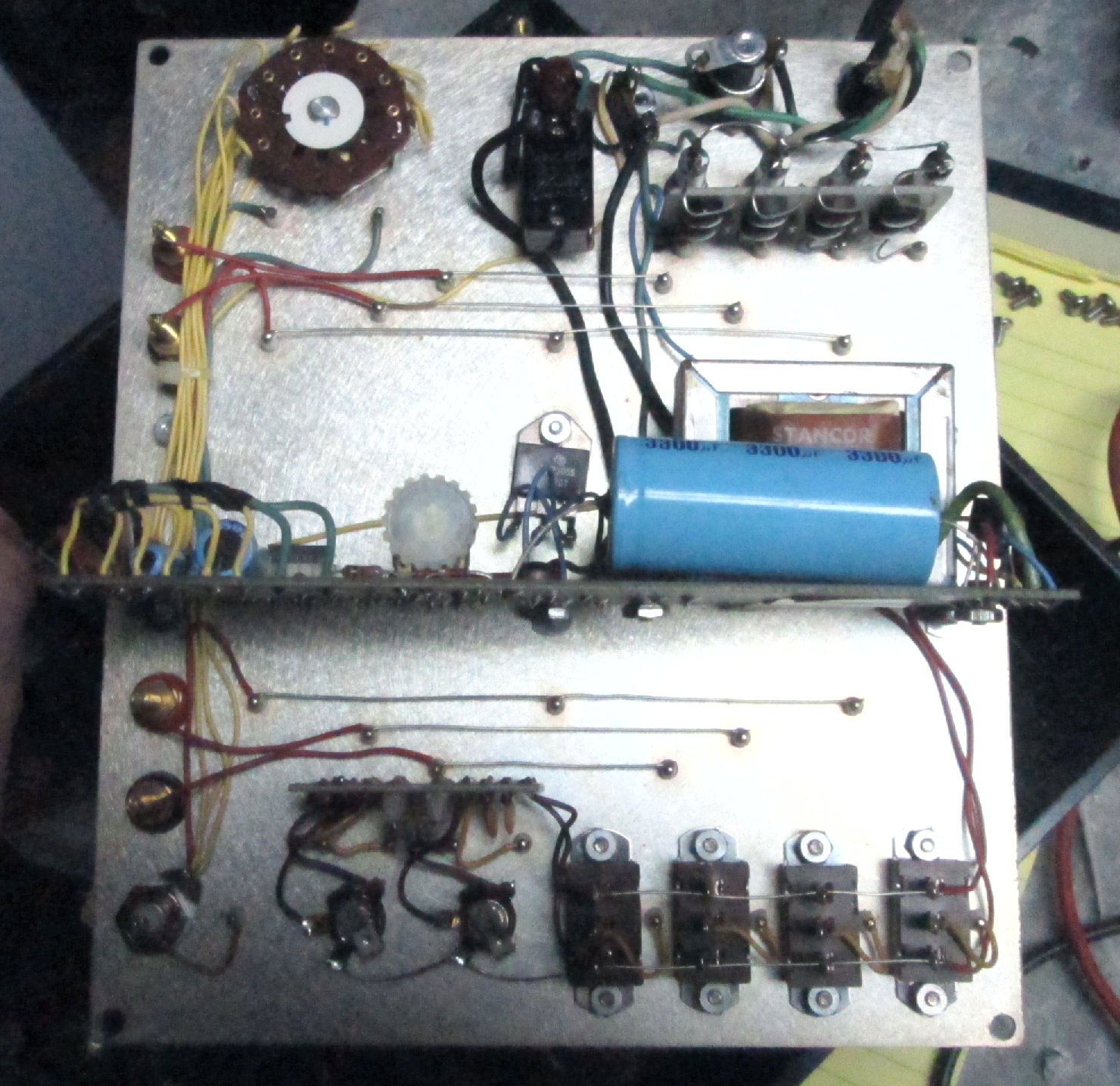
I went to a hamfest in the Minneapolis/St. Paul area. I bought ... an E&L CD-1 CMOS/TTL Designer (similar to the Digi Designer 1). Here's a photo of what's inside. I cleaned it up, and initially it (mostly) works! I spent some time cleaning and fixing my CD-1, and got it all working. I couldn't find a manual for it online, but your manual for the DD-1 is close. The CD-1 seems to be less common than the DD-1.
The CD-1 front panel looks just like the DD-1, but has an additional TTL/CMOS slide switch, a slide pot labeled VOLTS, and an extra position for the CLOCK switch labeled EXT with two extra terminals for an external capacitor to set the frequency.
The TTL/CMOS switch selects between a fixed 5v supply, and a variable 2-16v supply (adjusted with the linear pot on the left side of the front panel). The 4 logic switches output either 0v or supply voltage. All are noisy/intermittent, but at least they work. Cleaning will probably help. Regardless of the supply voltage, the 4 LED indicators use TTL levels.
"The square wave generator works, but some of the frequencies are quite far off. In the EXT position, the external capacitor can run it at anything from below 1 Hz to over 1 MHz. Regardless of the supply voltage, it outputs TTL levels.
"The binding posts and BNC connectors are just adapters; no circuitry is attached. One of the two debounced "pulse" pushbuttons didn't work.
The thing was tedious to fix, in part because the PCB has an opaque black soldermask, so you can't see the traces. I found 3 open traces (fixed with patch wires). The 6 ICs are socketed, which helped.
I replaced the broken AC illuminated power switch. Amazingly, I had an exact replacement for it.
[There's a TTL/CMOS DC power switch.] In the TTL position, the supply voltage is 5v, and it appears to work exactly the same as the DD-1. In the CMOS position, the supply voltage is variable from 1.4v to 16v set with the VOLTS slide pot. The CLOCK, PULSERS, LOGIC SWITCHES, use +5 volts for power but buffer their outputs to [either +5V or the] DC voltage level set by the VOLTS pot.
The design is otherwise pretty naive, an early or beginner's design, IC date codes are 1973, 1974, and 1976, so it was probably built around 1976. Six ICs, but only one 0.01uF bypass cap. The PULSER switch inputs are either grounded by the switch, or left floating (so I added 10k pull-ups to VCC). Unused TTL inputs are just left floating, or tied directly to VCC (instead of through a resistor, which should be done for 74xx ICs).
The design of the PULSERS is screwy. The pushbuttons go to the D inputs of a 7474 flip-flop. The 7474 is then clocked by the 60Hz AC line frequency! So the outputs only update at each rising edge of the AC line. However, there is no noise filtering on the AC, so the rising edges include power-line noise. If you happen to push the button just as the AC line is rising, you still get output glitches (brief pulses).
The CLOCK frequencies were way off (over 2:1). 3 of them used electolytics, which were way off value. The circuit is basically the same as your DD-1 schematic. It's not very stable, and drifts with supply voltage, temperature, and if the 7414 is changed. But good enough for breadboarding, I guess.
The two Pulser switches control a 7474 dual flip flop. Its four outputs (Q and /Q) go to 7406 open-collector inverters. The 7474 and 7406 are powered by +5v. The collector outputs of the 7406 inverters are pulled up to +V by 1k resistors. So the pulser outputs are either +5v (TTL) or +V (CMOS). The same is done for the CLOCK outputs.
The TTL/CMOS switch connects [all] the 7406 [collector 1K] pullups to +5v or +V. And, all the ICs are powered by +5v (except the uA723 regulator for the +V supply).
The Logic LEDs inputs go to a CMOS 4049 buffer with a 470k resistor to GND. The outputs of the 4049 are buffered by 7406's with open collectors to drive the LEDs. All CMOS 4049's, and even the modern 74HC4049 variants have no input protection diode from their inputs to VCC. This means the 4049's can be powered at 5v, but have inputs as high as 15-20v (depending on the specific part). But since it's powered at 5v, the input switching threshold is still about 1/2 of Vcc supply voltage (i.e. about 2.5v with a 5v supply).
They could have used [a second AC diode] bridge to get 7~8vdc for the +5v supply, [to reduce heat from the LM340 regulator.] But they didn't. The +5v regulator is screwed to the aluminum front panel, so it has a big heatsink (and needs it)!
The Logic LEDs inputs only draw about 10ua at +5v (TTL), or 30ua at +15v (CMOS). But they powered the 4049 at +5v, so the input switching threshold is always ~2.5v in both TTL or CMOS modes.
Another screwy thing: The Logic LEDs are connected between GND and the 7406 outputs. They then had 150 ohm pull-ups to +5v. When the 7406 output goes low, it shorts the LED to turn it off. This also means that each Logic LED circuit draws about 25ma regardless of whether the LED is on or off!
Yet another: The Clock circuit is always running, so it is always spiking the +5v supply. Since there is only a single 0.01uF bypass cap for the whole board, the +5v supply is noisy. These noise spikes get added onto the 60Hz signal they used to clock the 7474's. When those noise spikes happen during the 60 Hz's rising edge, the Pulser's "debounced" pushbuttons aren't really debounced.
The power transformer must have gotten hot at some point; it was screwed directly to the plastic case, which had partially melted. I added a little metal heat spreader plate to (hopefully) prevent further damage.
The power transformer gets hot because it's a 6.3vac 1a unit that feeds a voltage doubler to produce a 17v supply. An LM340 regulator then knocks it down to 5v (TTL), or a uA723 regulates it to the voltage set by the VOLTS pot (CMOS). The 5v load was about 200mA even without any breadboard loads.
The four LAMPS circuits each drew 25ma regardless of whether the LEDs are on or off. I replaced the LEDs with modern higher-efficiency parts, and increased the current limiting resistors by 10:1. Each LED now draws 2ma, not 25ma. That cut the total 5v load in half, and the new LEDs are brighter anyway. - Lee Hart
I've used the CD1 a few times to breadboard things. I added more Vcc bypass caps, as the noise from the 5v supply was pretty bad without them (it had just a single 0.01uF bypass in the whole thing). - Lee Hart
![[digi designer]](dd_panel.jpg)
The front panel has the E&L breadboard, and connections to the 5V power supply, four logic-display lamps, two logic-conditioned buttons, four logic switches (not conditioned).
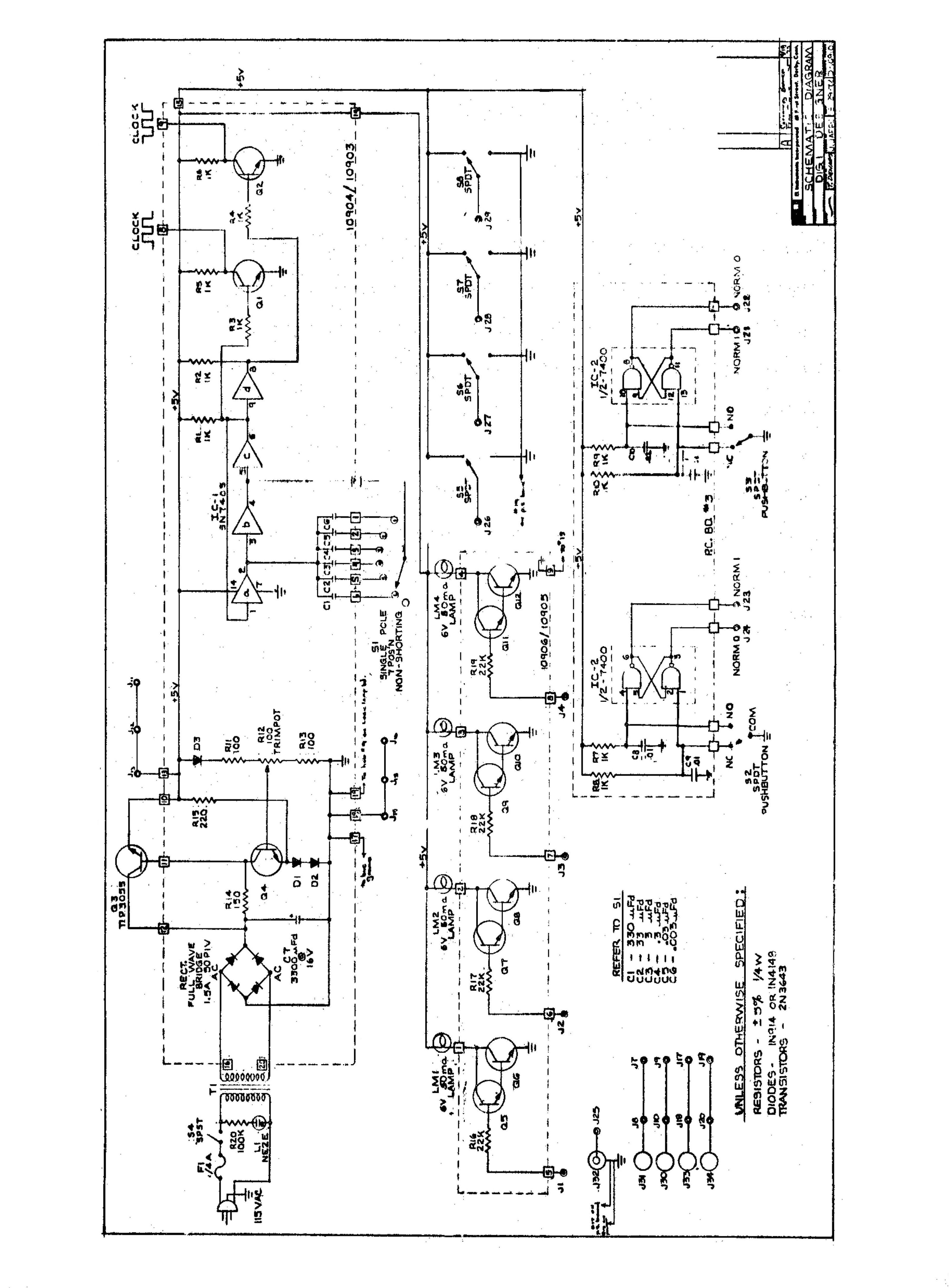
Here's the E&L Digi Designer manual. There's a schematic inside the manual.
interior photos:
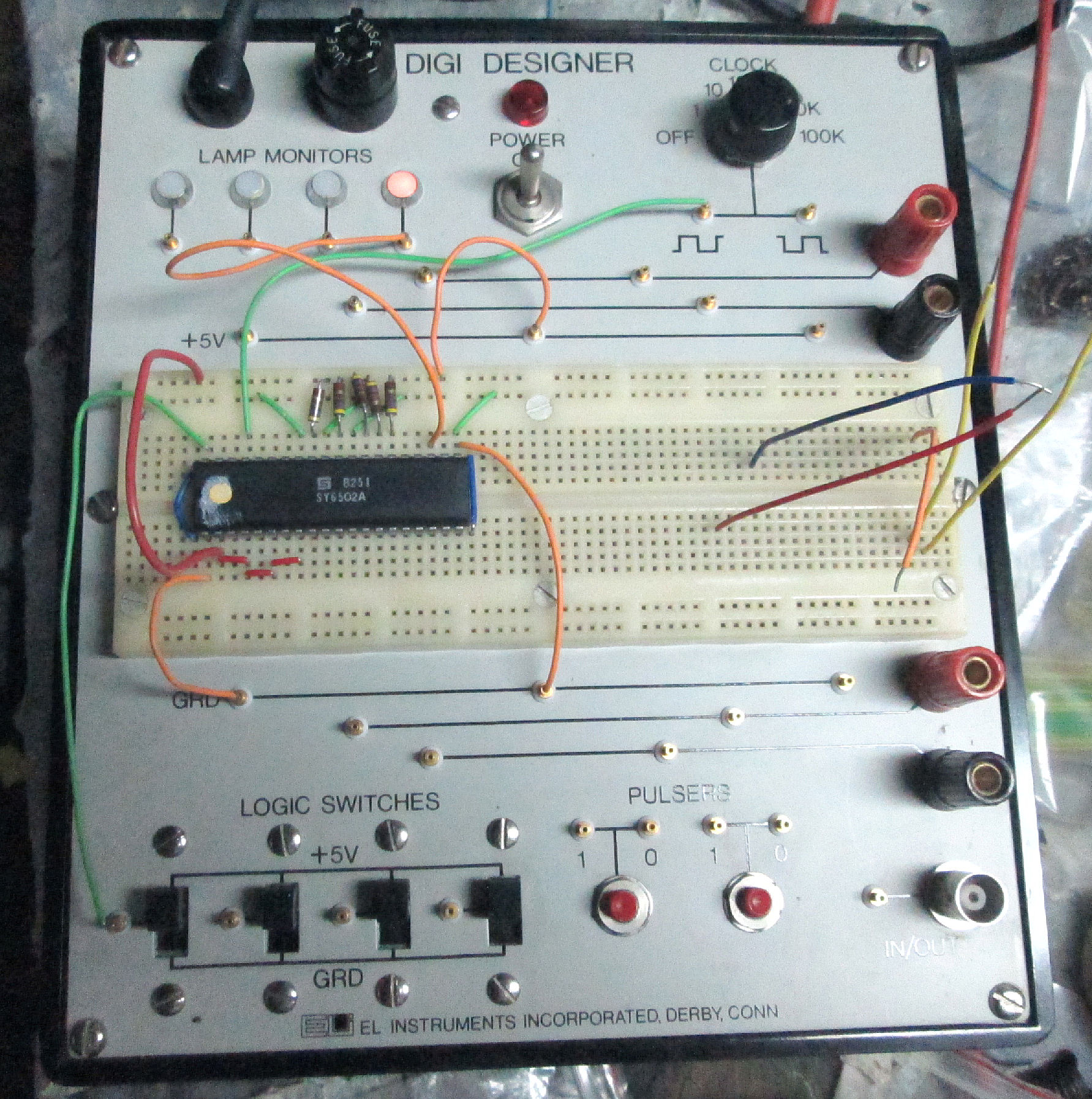
The front panel for reference
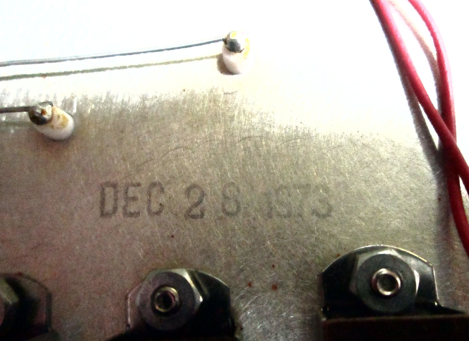
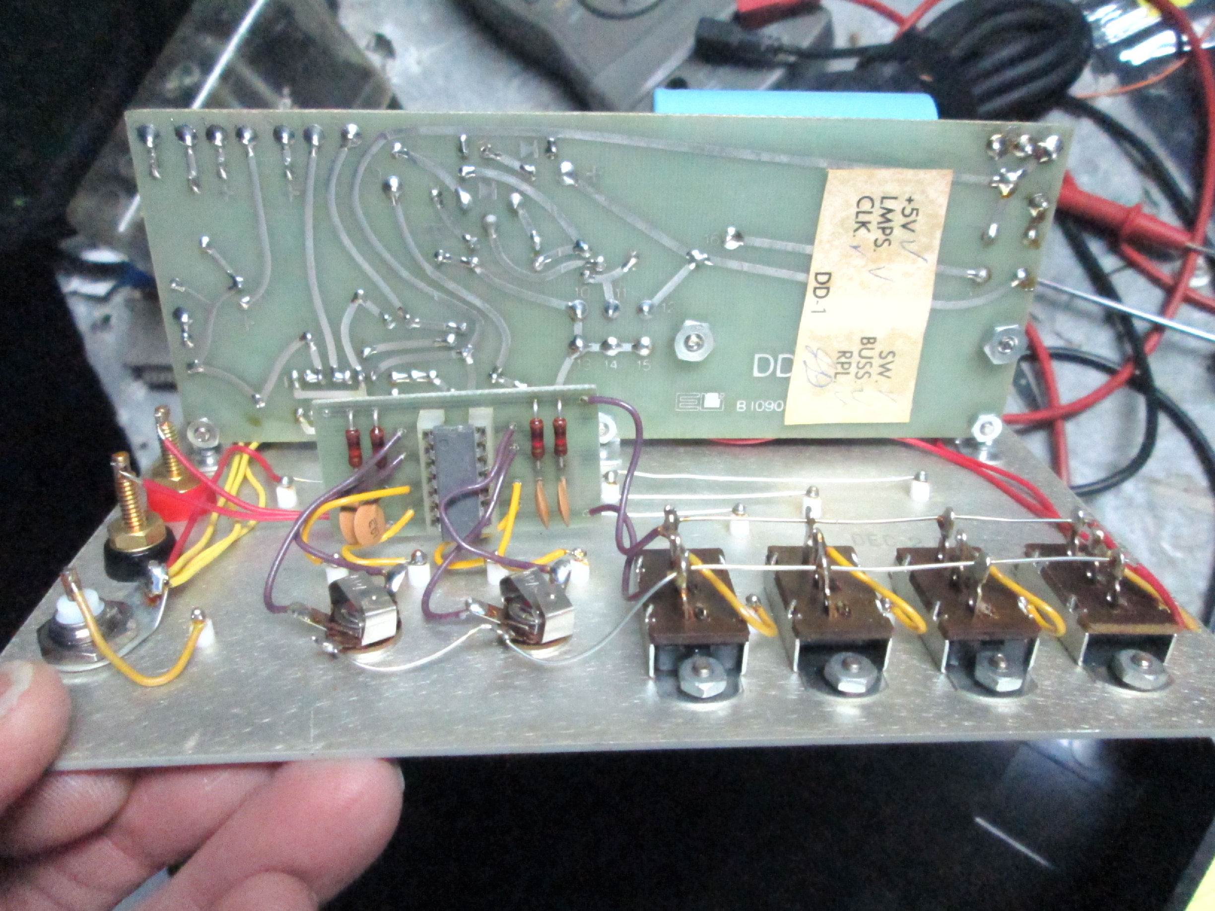
the back of the front panel
The back of the front-panel has a date stamp in black ink of "DEC 28 1973".
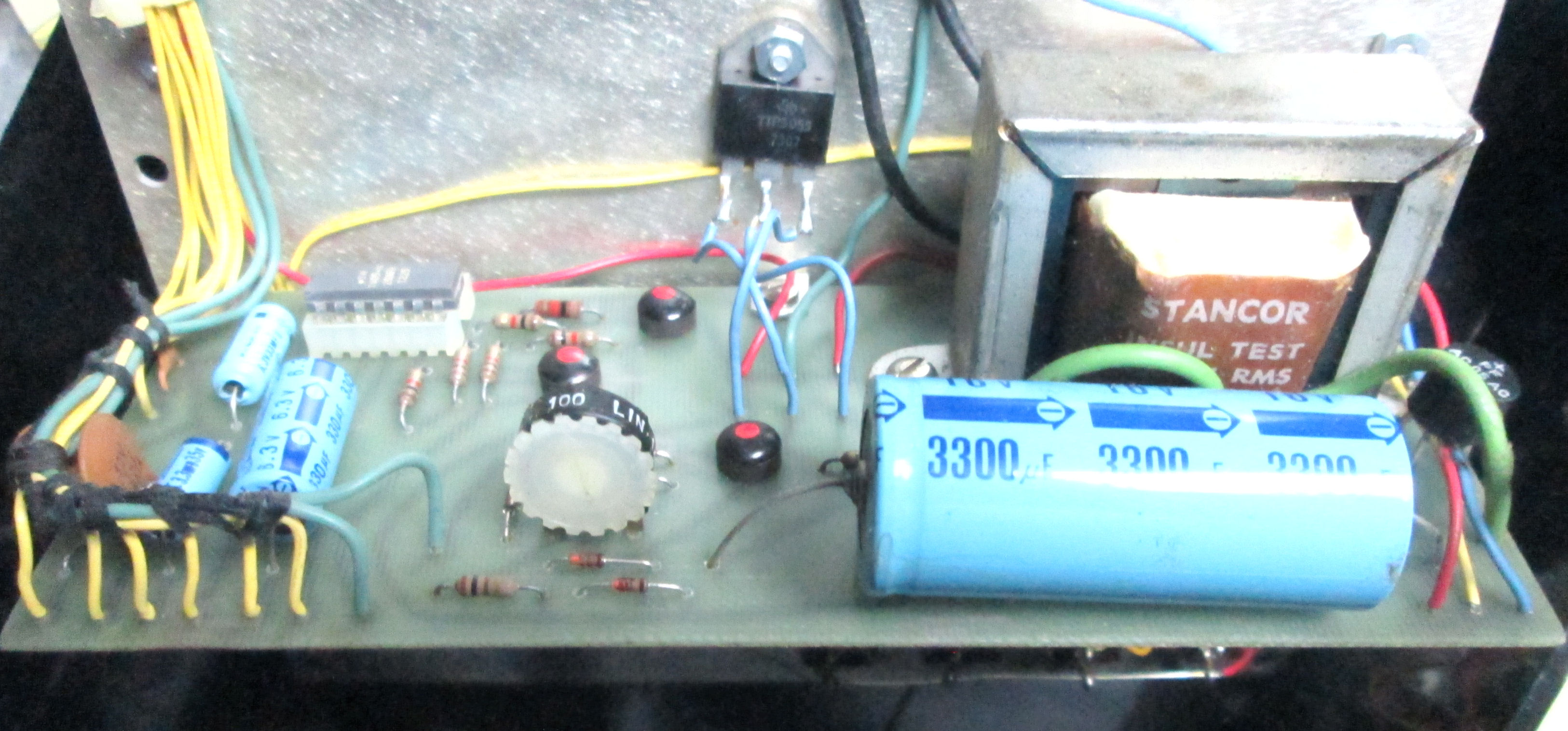
the PC board for DC power The trimpot adjusts the 5V regulator.
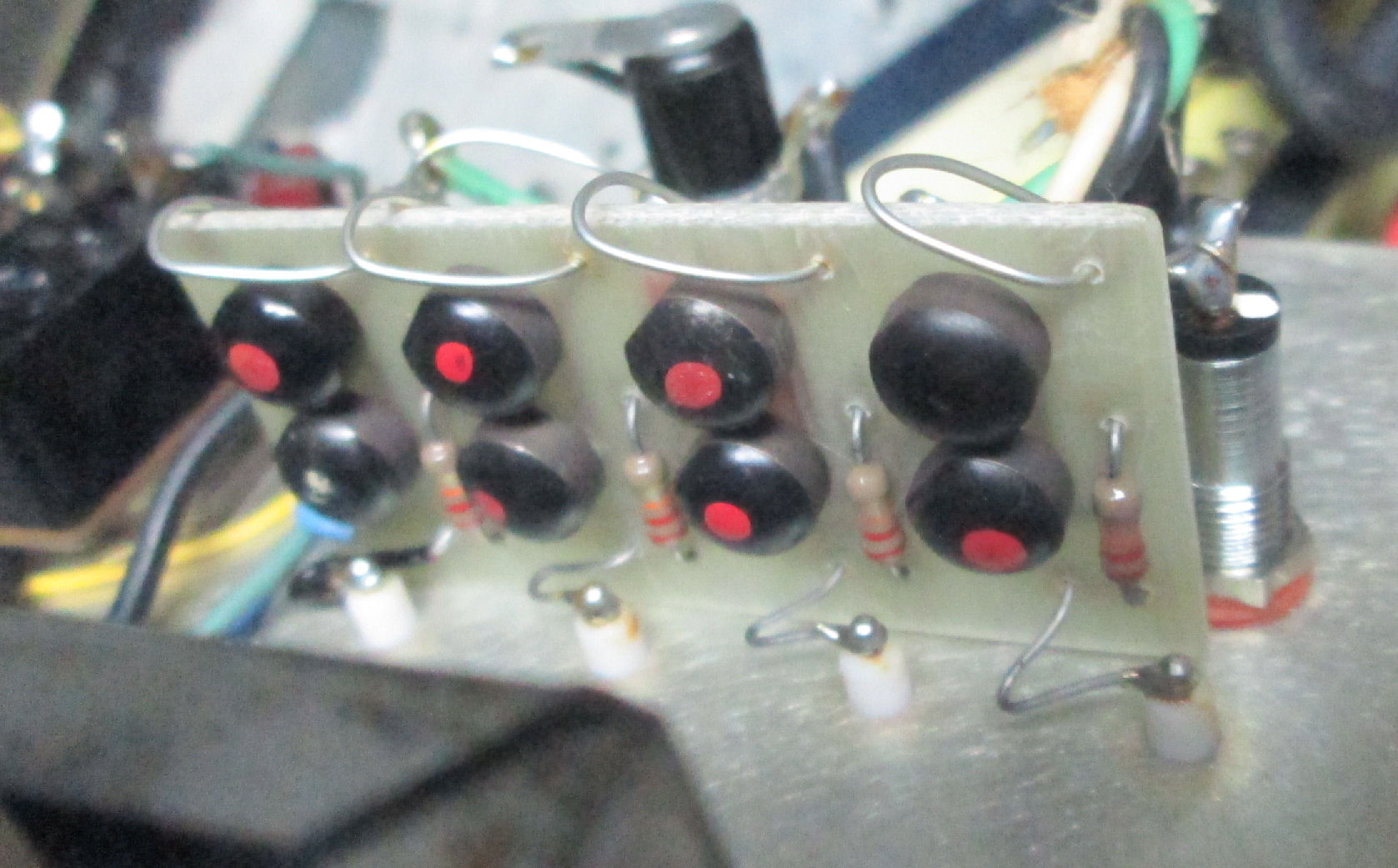
under the PC board to view the buttons and switches
the small board for the lamp logic transistors
restoration was uneventful. I cleaned up the front panel, and put DeOxit on the switches and buttons. I used a Variac to slowly raise AC input voltage, to reform the caps. None of them seemed to be damaged, they are all low-voltage electrolytics. When the unit operated at full AC line voltage (120V), I confirmed the DC power supply output was about 5.0V unloaded. It needed a little adjustment. Here's the performance of the DC regulator versus AC voltage:
AC volts  91.5   98   104   110  116  122
DC volts   5.0   5.1  5.15  5.17 5.2  5.22
I adjusted to get 5.0V at 120VAC no load.
Purpose: I revived this breadboard, to wire up a 6502 CPU circuit, to test several questionable 65C02 microprocessors. Here's the circuit I wired. It's a simple way to exercise an 8-bit classic processor. The eight data lines are either tied low or pulled up with convenient resistors (270 ohms here) to force the data lines to a "NOP" instruction. The processor clock, is wired to the square-wave generator. The 6502 reset is tied to one of the logic switches. Other 6502 lines are grounded, tied to 5-volts, or left open as needed to run the processor.
By connecting the logic lamp to various 6502 address lines, I can see if the processor is running through the address space by observing the address lines toggle from high to low on a regular cycle. For more details and my results, check this linked Web page.
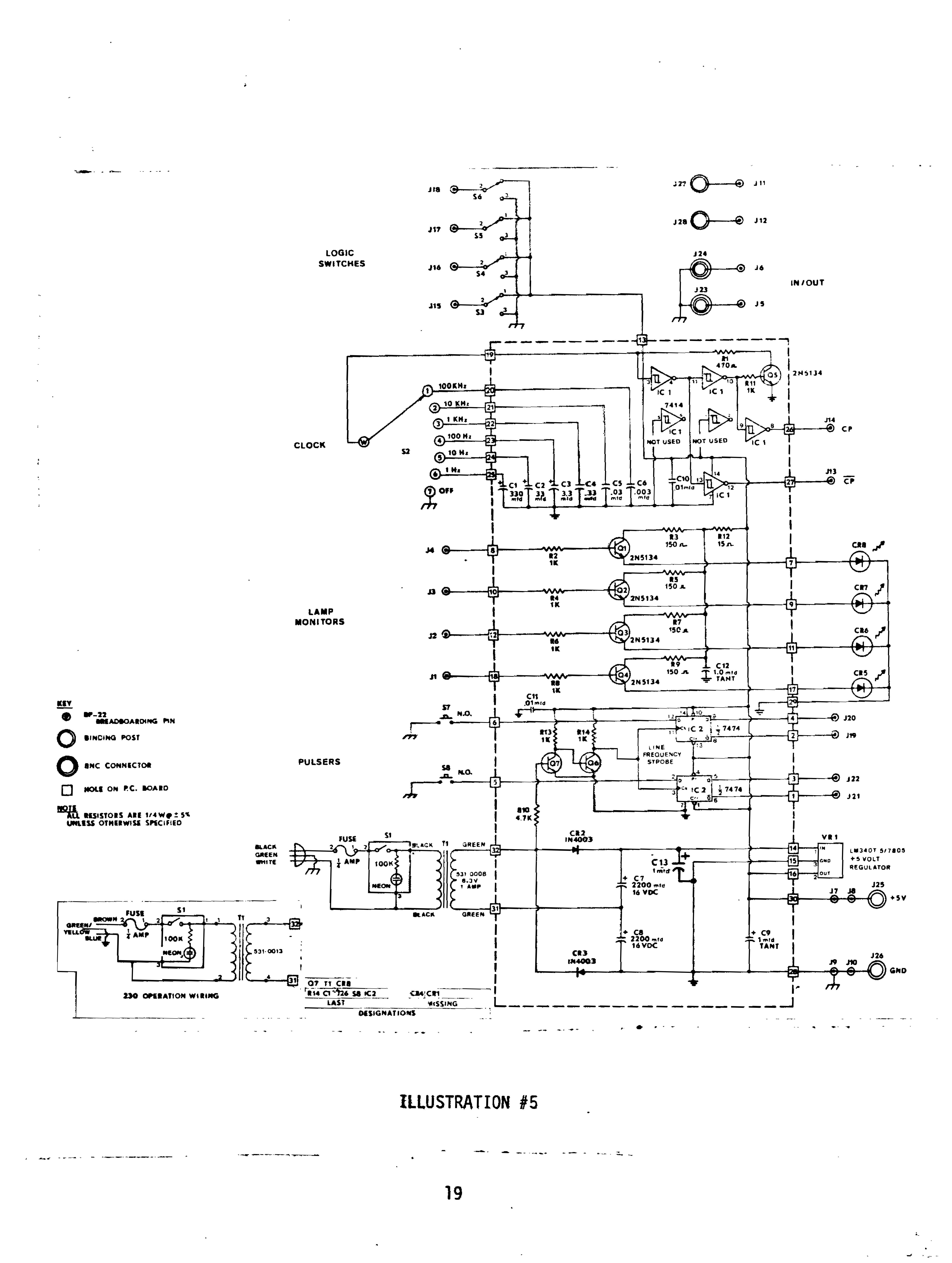
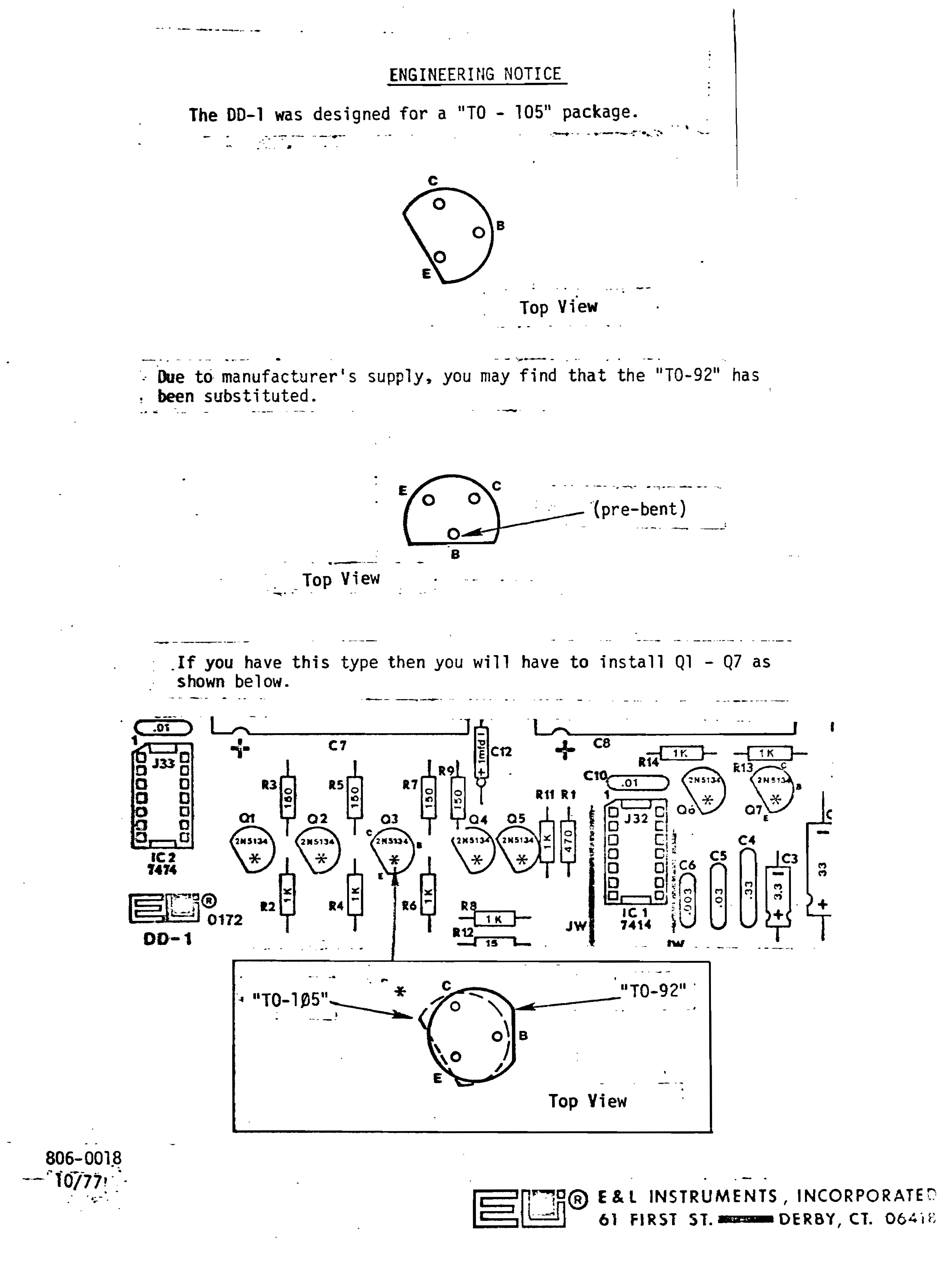
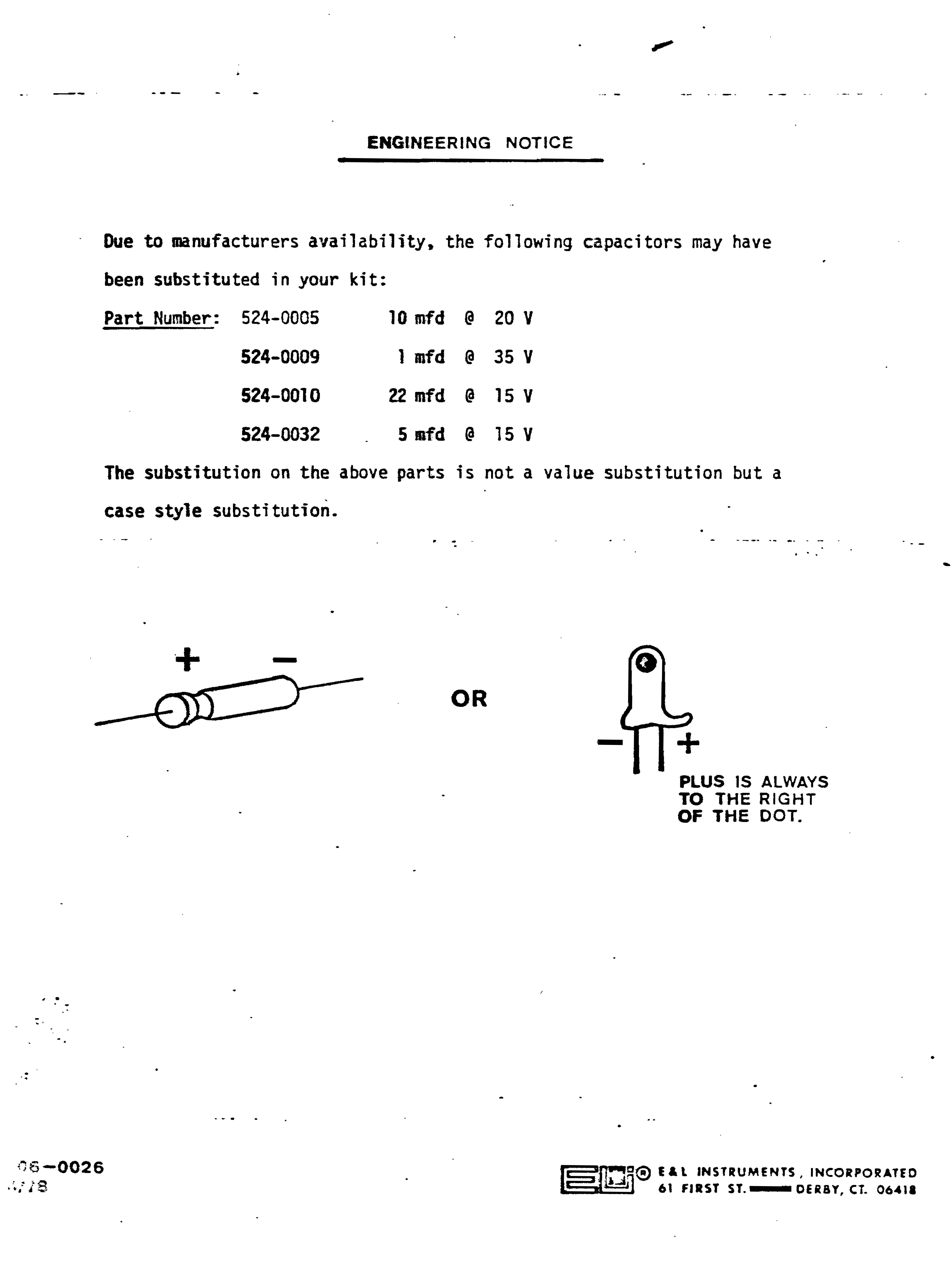
Here's an E&L Digi Designer 1 manual. It's a redesign but similar to the Digi Designer. There's a schematic inside the manual. There's also two enginering notes of component changes, here and here.
![[E&L]](el_cdp01.jpg)
![[E&L]](el_cdp01_2.jpg)
Here's another E&L breadboard product I have. Work is pending. No docs. An E&L Circuit Designer Powerpack CDP-01. Lots of useful voltages, even AC, for analog work. NOte: the two fuses are BUSS MDL 5 slow-blo . - Herb
![[E&L CD1]](el_opamp.jpg)
Here's another E&L breadboard products I have. Work is pending. No docs. An E&L Opamp Designer, of course for op-amps. It has a 5-volt supply for TTL work. - Herb
![[E&L MAT]](e&l_mat_1.jpg)
![[E&L MAT]](e&l_mat_0.jpg)
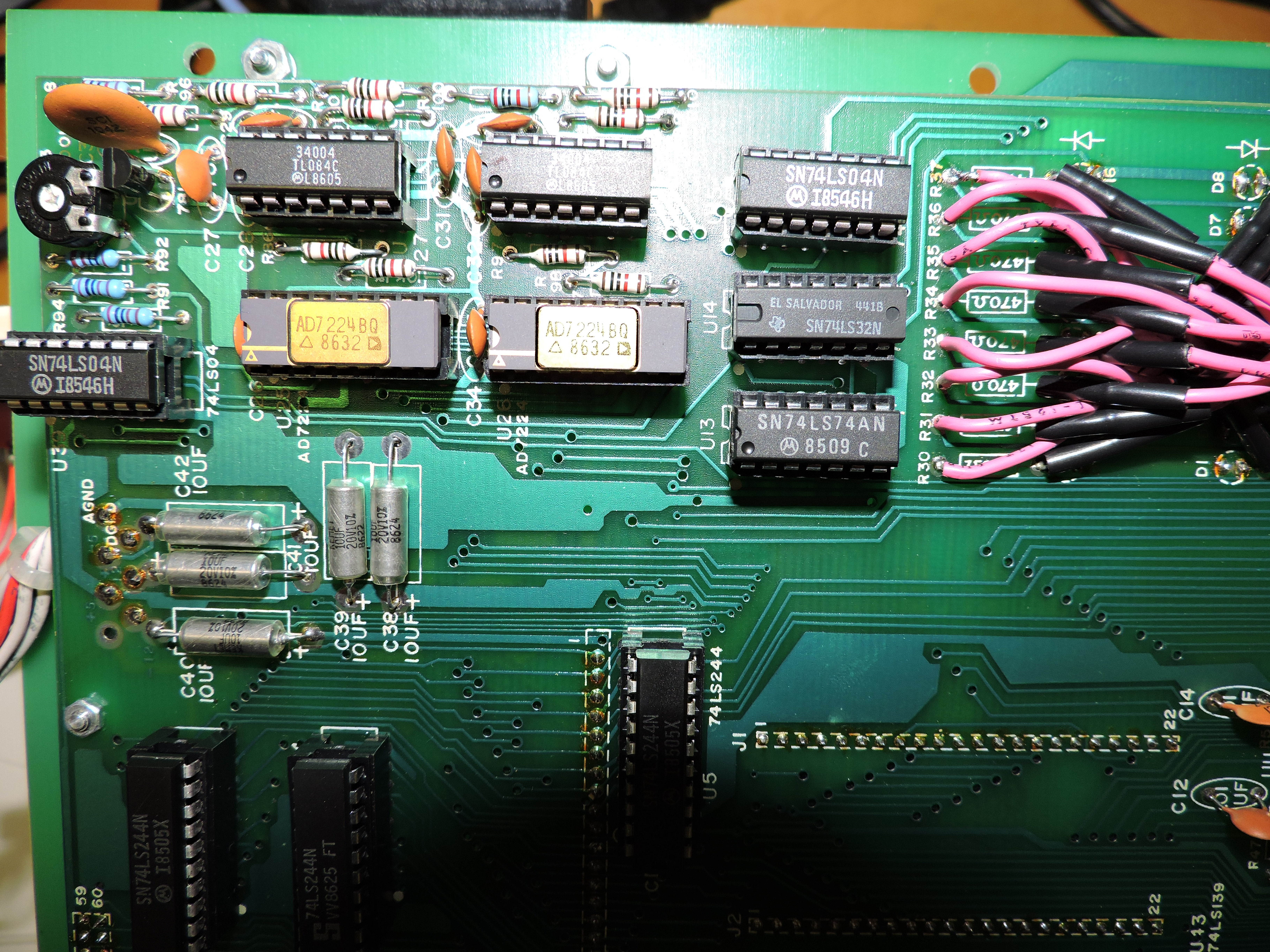
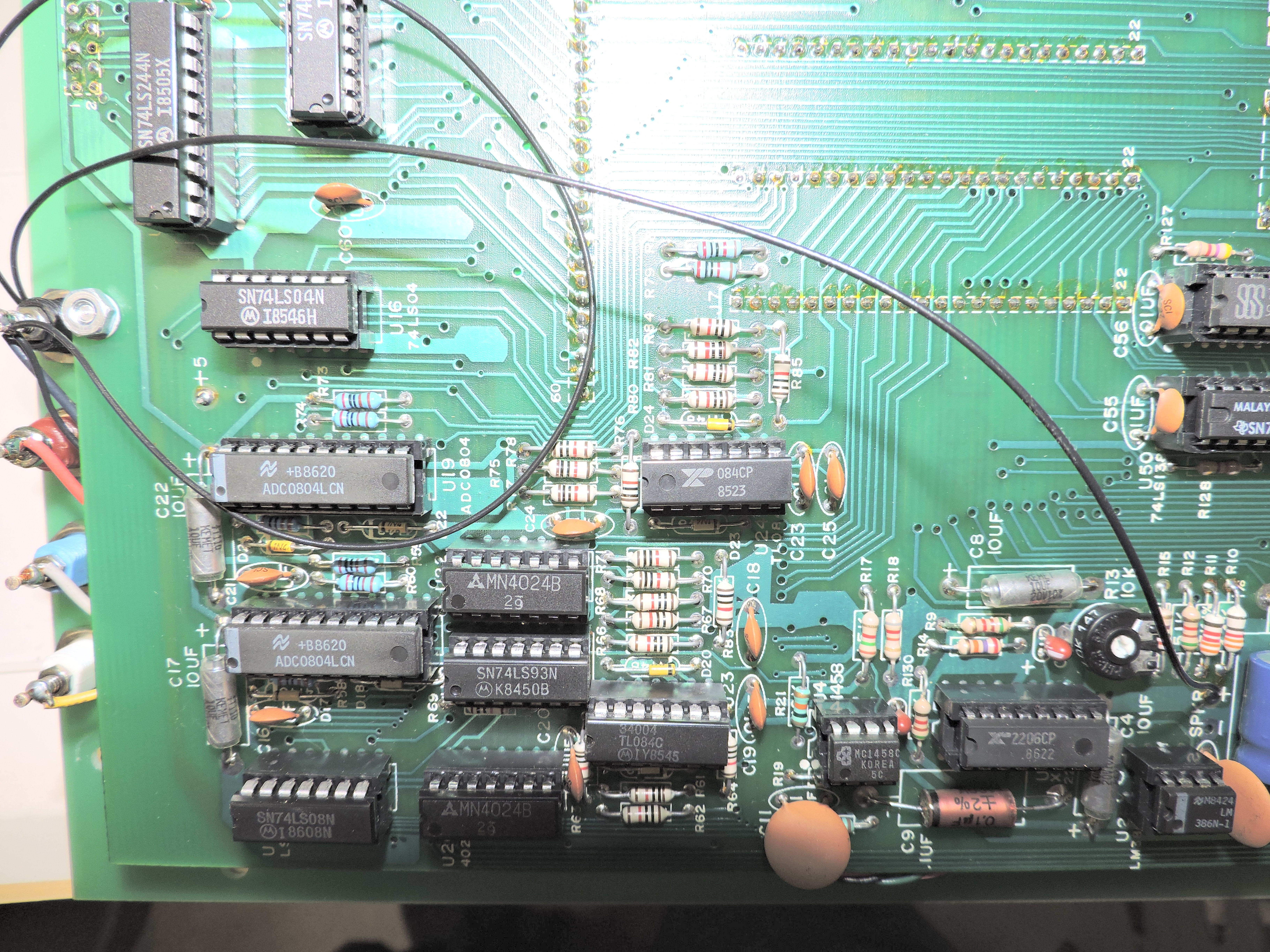
In Dec 2025, John Ott contacted me with photos of his "MAT Microcomputer Applications Trainer" a breadboard product produced by "E&L Instruments, An Interplex Electronics Company". He could not find any information on the Web about this product, and so he introduced me to it. I also could not find any Web archived information, only one reference in a document. Component dates suggest this was constructed in 1986. Of course, if anyone reading this has further information, please contact me, see the end of this Web page.
By inspection of the breadboard side, there's a flat-cable connector labeled "computer interface". That likely connects the digital side of these circuits to a microcomputer for software operation. The central breadboard has a list of signals that probably correspond to pins on the computer interface. Means to select I/O addresses for the digital devices (via the computer interface or maybe manually) is in the "I/O DECODE" section. There's some memory selection with two green ZIP sockets for 28-pin bytewide devices either ROM or RAM. There's digital I/Os for LEDs and DIP switches; and D/A and A/D converter selections. All these are breadboard strips wire-accessable to the central breadboard.
Photos inside the unitof the circuitboard , show components with date codes of 1985-86. There are some Analog Devices chips inside, AD7224BQ, an 8-bit digital-to-analog converter; and two ADC0804LCN which are an 8-bit D-to-A converter. There's other analog components and some TTL logic chips. Search of data sheets for the various devices should establish their relation to the patchboards on the "front panel".
- Herb
![[E&L 8080]](e&l_8080_box.jpg)
I acquired this 8080 breadboarding product, the E&L Mini Micro Designer MMD-1 with Intel 8080, in late 2023. Repair is pending. It includes a 1702 ROM with serial monitor, and decoded I/O ports. One such port has some 7-segment displays. Docs can be found in Web archives. It was covered in Radio Electronics Magazine, May June July 1976, by Jon Titus as the "Dyna-Micro" computer, very similar
design; and later in the BugBook paperback series (look it up). - Herb
![[Elenco]](elenco_done.jpg)
I acquired an Elenco XK-500 in Dec 2024. The manual says it was produced in 1991. Sold to me as damaged, I carefully powered it up with a Variac to monitor the voltage regulators (+5. +12, -12, variable plus/minus). But I saw most of the problem was poor construction probably shorting out either the regulators or the transformer AC outputs. With those resolved, the unit operated as designed.
The unit includes a XR2206 function generator IC that
produces square, triangle, and sine waves at audio frequencies. From a manual online,
here's page 1 and page 2 of the schematic. The full manual is here.
Inspection upon reciept found an interior of tangled leads and wires. NOtes by the seller suggested shorts which blew fuses. one side and another side where the various 3-terminal regulators likely shorted themselves. Simplest repair was to spread out the leads and then see if there were DC voltage failures, then signal failures from the XR2206 generator. While resolving the regulator wiring, I drew the layout of the regulators on either side of the case.
Along the way, I observed a mechanical problem with the Molex connnector below the DC voltage adjustment pots. That connector provides access to raw AC and variable DC. I observed the connector was unsecured in the panel, to the point where wires were shorting onto the pan and with each other. See this view of the unrepaired connector. amdf this view of shorting to panel.
My fixes were 1) to reroute two wires so that only single wires went to the Molex pins, and 2) secure the Molex connector to the panel. Simplest fix was to use silicone sealant around the connector, to both anchor & elevate the plastic body and to insulate the pins. The result also flattened the Molex connector to the panel surface. Here's the silicone anchoring on the connector. I waited a day for the silicone to harden.
With those repairs completed and the voltage regulators and their leads identified, I started electrical testing. To reform the caps and reduce risk, I connected a Variac to the AC side and monitored DC voltages as I increased AC voltage. I'm used to watching 3-terminal regulators deal with undervoltage AC, they don't start outputting DC voltage until the input DC is within a few volts of output voltage. Meanwhile I'd spot any shorts either by zero-voltage or a warm regulator. Fortunately, no shorts occurred, the caps seemed nominal, and I was able to get to operating voltage over a few hours testing. The +5 regulator seems to run a little low (4.85V or so), but that's close enough to operate the generator and the local TTL logic. The variable voltage controls did their job. Look at my regulator drawing to see the various DC voltages.
With DC voltages acceptable, I used my oscilloscope to observe the operation of the XR2206 generator. The square, triangle, and sine waveforms were all reasonable; the frequency decade and variable controls opearated reasonable. There's a "flat" on the sine wave; probably needs some kind of DC gain adjustment. The DC offset for sine only had a limited range. These are things I can tweak later.
I also checked the operation of the logic & data witches and logic LEDs. They worked, although the logic switches were cheap and sometimes loose. The eight data switches are just wired to +5V or ground, no conditioning; the two logic switches were on TTL gates. There's simple resistors on the LEDs, they all lit. The breadboard labeling on the panel is ambiguous, it only applies to the topmost breadboard connector. That is, the designations above that top connector are for pins on the first uppermost row on that topmost connector. The designations below the top connector (Logic SW, Power, Modulation, Generator) are for the second row of pins, same connector.
At this point in mid-December 2024, the Elenco 500 is mostly operational. I cleaned up the front panel as shown in my final photo, and put the unit aside for later work or use. I've not mentioned, that the plastic cover is completely torn off. I Duct-taped a hinge for it. Either I'll replace the case or create some kind of plastic hinge. - Herb
![[DeVry]](DeVry_panel.jpg)
This DeVry (also Bell and Howell) product is owned and was serviced by Lee Hart in March 2023. The photos are his unless noted. The black peforated panel, is one of several which interlock to form the "breadboard" put on the panel. There were sets of blocks with the kit, that had embedded components or sockets that plugged into the holes. Components include vacuum tube sockets, as the kit was designed to teach about tube and transistor circuits.
I found this photo of some B&H wire blocks. Also, here's a B&H catalog description of the product. - Herb
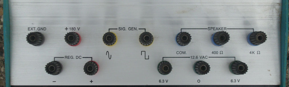
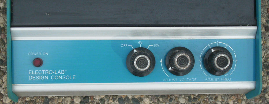
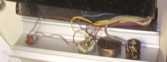
The cabinet upper panel, has posts as shown here wired to the 30V DC adjustable power supply, the +180V DC supply, the 6.3/12V AC transformer. Also, wired to a speaker through an audio transformer (400 / 4K ohms impedance), a sine / squarewave generator, and ground. The lower panel controls are for OFF-6V-30V DC selection, a DC voltage adjustment, and frequency of the audio oscillator.
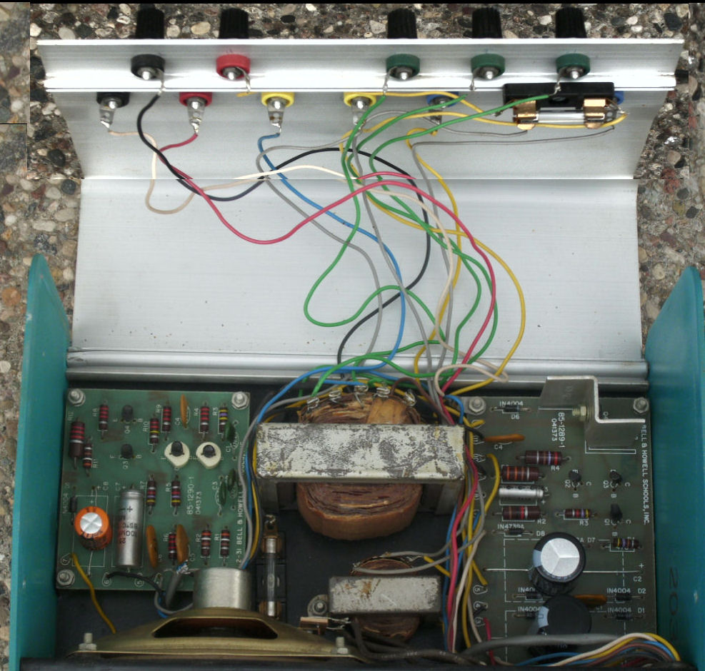
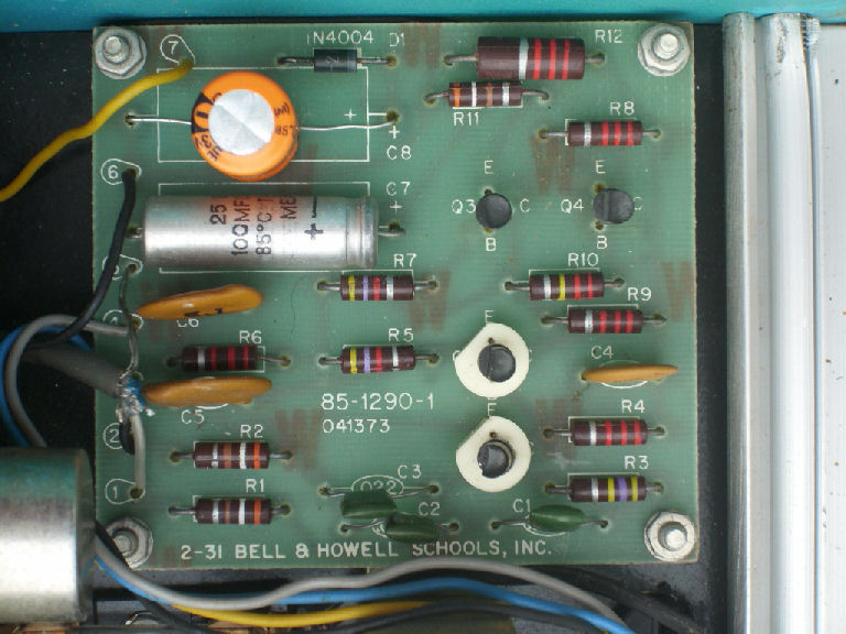
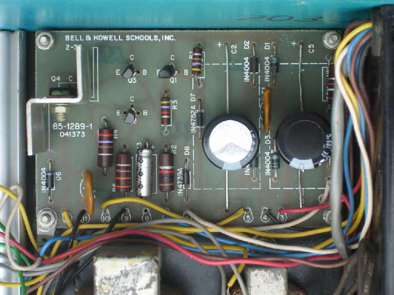
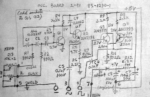
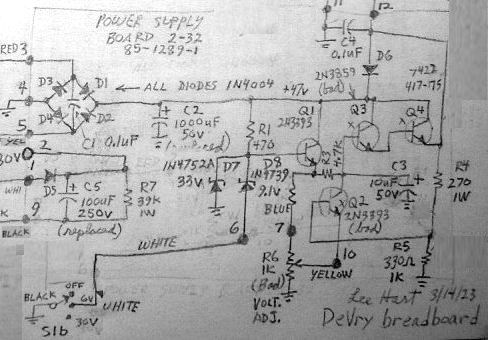
Inside the upper console are two circuit boards, a speaker, two transformers, and other parts. The board near the speaker is the oscillator. The board opposite is the power supply. Inside the lower console are the controls for power and voltage, the frequency select and frequency adjust potentiometer.
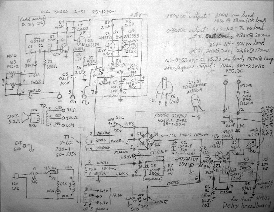
Here's the DeVry schematic, traced out by Lee Hart. There's a oscillator board schematic and a DC power board schematic I cut out for convenience. Here's a parts list with more details.
The construction manual for this product, is a little scarce, and not available online as a free document as of 2023. DeVry, and Bell and Howell Schools, produced a series of educational project manuals for this product.
Lee Hart, after tracing the circuits, tested and replaced a number of components. Some were likely damaged by time, some possibly by accidentally connecting the high-voltage output to the oscillator or low-voltage supply. The 180V output is un-fused! Lee's hand-drawn schematic has notes about replaced components.
His plans for use, are to use small E&L style breadboards mounted on magnets on sticky-tape, to hold to the metal surface where the original plastic "breadboard" panels were in use. Other major components, like vacuum tube sockets, will be on stronger magnetics. Then wires from the components can be wired to the breadboards which will hold smaller components.
![[DeVry]](DeVry-TubeSockets.jpg)
April 2, Lee Hart: "I built a couple tube sockets for breadboarding on the DeVry. I also added a cheap little DVM since the "regulated" 0-30v supply isn't very well regulated."
"The tube sockets use the smallest size solderless breadboard. They have two mounting holes on the ends, so I used them to mount the tube sockets with screws on standoffs. I soldered wires onto the tube socket pins, then plugged them into holes on the solderless breadboard. The bottom of each breadboard has double-sided thick foam tape, which mounts semi-flexible "rubber" sheet magnet material, to stick it to the steel base-plate on the DeVry."
"The voltmeter is a $3.95 one from Electronic Goldmine. Pretty poor; no docs, untraceable circuit, not very accurate. It has a tiny trimpot that can set it to be accurate at *one* voltage; but then it's off everywhere else. The best I could do is set it to be 0.2-0.3v low across its range. But at least I'll have *some* idea of what the output voltage is. " - Lee Hart
- edited by Herb Johnson from notes and photos of Lee Hart, March-April 2023, and later notes.
![[HOPE VCF]](VCF_Hope_2024_display.jpg)
On July 25 2024, VCFed-Midatlantic member Jeffrey Jonas posted in their email list about that group's exhibit at the NYC HOPE (hackers conference) It included vintage breadboards and single-board computers of the 8-bit era. I found an image of the VCF exhibit on X. Jeff provided further details. - Herb Johnson
I had a blast staffing VCF's exhibit at the 2024 NYC HOPE conference on Friday & Saturday [July 12-13 2024]. Many thanks to Doug [Crawford VCFed-Mid museum manager], Dean, Jeff Brace [VCF vice president, on-site official] for carpooling and making such an engaging exhibit.It was perfectly on-target for the audience, limited by what fits in one car. I was in my element, meeting folks I know from Unigroup (NYC Unix/Linux professional society), NJ Linux group and other circles of friends.
The exhibit started with the Discrete Transistor 555 and a breadboarded 555, showing how the first chips were only dozens of transistors. The Bell & Howell chip trainer's flip-flops were wired as a binary counter next to a single chip counter doing essentially the same thing. That got a LOT of attention since it vividly illustrated how the building-blocks of logic gates makes for larger useful elements.
Then the microprocessor trainers: 6502, 8080, 8085. Folks adored running the ROM demos via the hex keypads and 7 segment displays.
The Apple 1 replica got a lot of attention, particularly with the SD-card cassette emulator instantly loading games and such. Some folks really enjoyed using the WOZ monitor and peeking/poking into RAM.
The PET, GRID and other [vintage microcomputers] got a lot of love too, particularly the GRID's plasma display. Some folks were into display tech, thus the geeking out over Doug's VFD and LED demo.
A really great outreach opportunity. - Jeff Jonas
Doug Crawford, who manages the VCF Museum, responded by saying the logic trainers will be added to the Museum's STEM activities. Ken, another VCF member, responded by confirming the exhibits attracted people with "expertize and stories" who might exhibit at VCF-East 2025, their annual vintage computer show. - Herb Johnson
The image from X is from a Vintage Computer Federation (@vcfederation) post
"What kind of computer does VCF have at HOPE this year?",
7:13 PM Jul 12, 2024 link here
Jeff Jonas provided another X Twitter link and the description below of the items. He has his own Web page on breadboards at this link.
 from left to right:

- the little white breadboard: a 555 timer chip blinking 2 leds
- The Discrete 555 Timer kit from Evil Mad Scientist Laboratories, blinking 2 leds
     https://shop.evilmadscientist.com/productsmenu/652
- Doug's Arduino demo of VFD and LED
- the DeVry Institute of Technology / Bell and Howell Schools trainer
with flip-flops wired as an 8 bit binary counter
- the PC board to the lower right with the knobs and red 7-segment LEDS
is a counter on a MSI-scale IC.
- the red PCB next to white breadboards
is an Arduino driving 2 red 8x8 LED displays.
One display counts in binary, the other is just eye-candy.
- then the microprocessor trainers on the next table extending into the horizon ;) - Jeff Jonas
Copyright © 2025 Herb Johnson